Rubber Expansion Joint Cracking at the Sphere-to-Collar Junction: A Full Failure Analysis and Our Manufacturing Fix
How we traced a 340mm crack on a DN200-1.0 wound-type rubber expansion joint back to a single design detail — and what we changed in production because of it.
Why This Failure Analysis Matters to Buyers
Most suppliers will tell you their rubber expansion joints are “high quality.” Few will show you the dissection data behind a field failure and walk you through exactly what went wrong and why. We think that transparency is what separates a real engineering partner from a catalog reseller — so here is one of our own case studies, in full.
The Problem: Field Failure on a DN200 Wound-Type Expansion Joint
A wound-type (convoluted/spherical carcass) rubber expansion joint — DN200-1.0, installed length L=180mm, with a 32mm-wide, 34mm-deep convolution — developed a 340mm crack at the junction where the sphere body meets the short neck/flange collar after a period of field service.
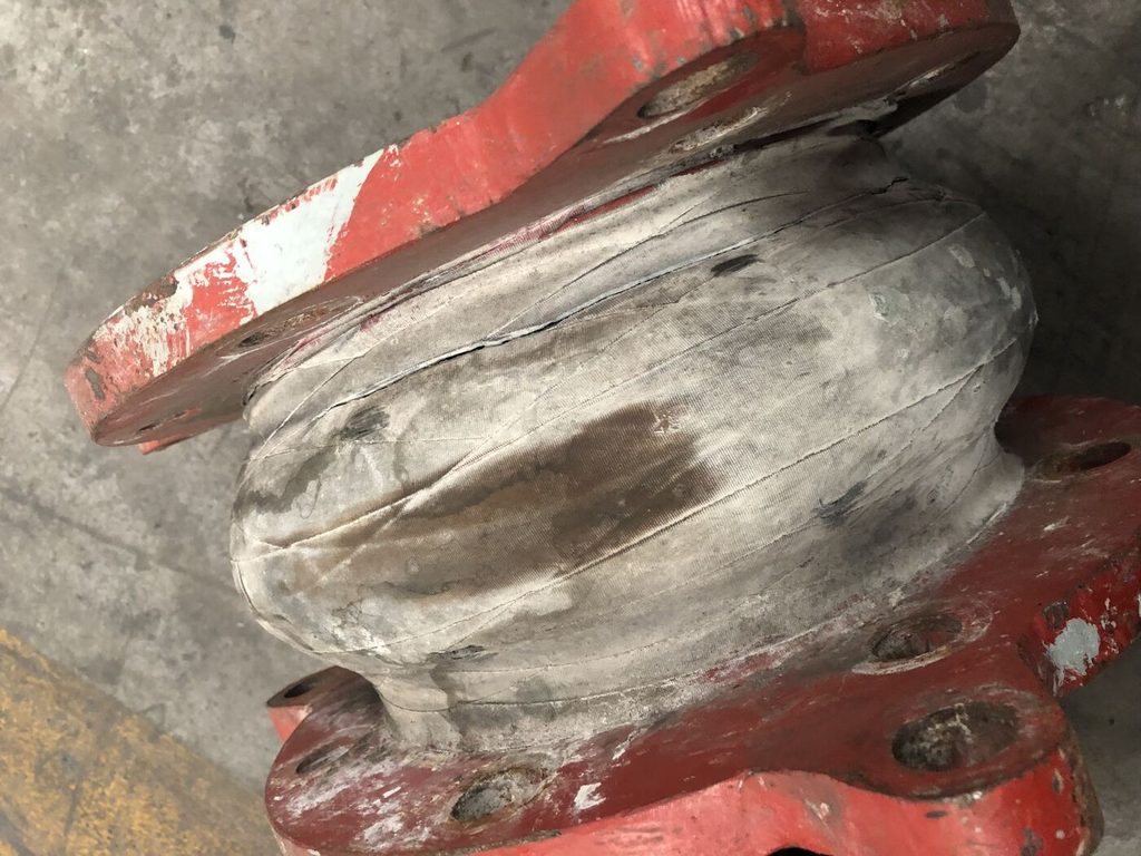
The failed unit as received: the crack runs along the sphere-to-neck transition zone.
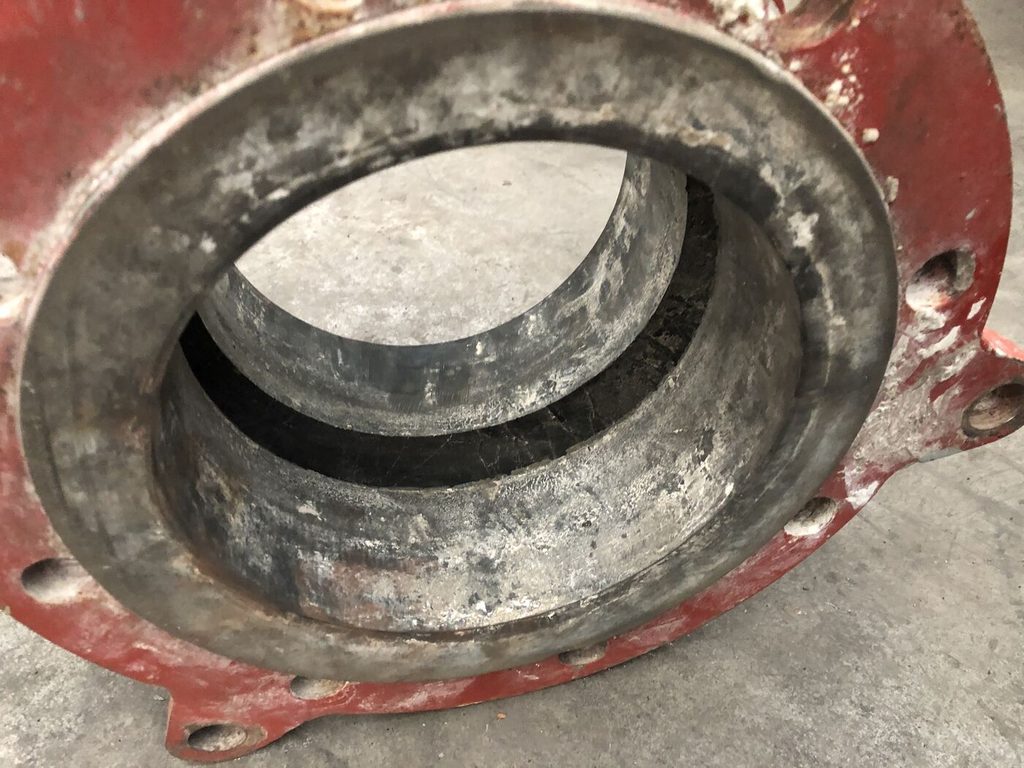
Close-up of the crack opening — the failure follows the sphere-to-collar splice line exactly.
Rather than simply replacing the part, we cut the failed unit apart and measured every layer to find the root cause.
Dissection Data
Rubber Hardness
| Location | Shore A Hardness |
|---|---|
| Sphere body, outer arc | 72 |
| Flange face | 68 |
Neck / Flange Collar Structure
| Measurement | Value |
|---|---|
| Cord-to-rubber adhesion strength | 119 N/cm |
| Neck total thickness | 21.8mm (inner liner 3.4mm + middle ply 4.5mm + outer cover 6.1mm) |
| Flange collar inner-bore rubber thickness | 12mm (2 cord plies) |
| Flange sealing face thickness | 7.3mm (1 cord ply) |
| Collar outer wall thickness | 9mm (2 cord plies) |
| Flange collar height | 40mm; collar wall ~3mm |
| Transition rubber between cord plies and collar | ~1–2mm |
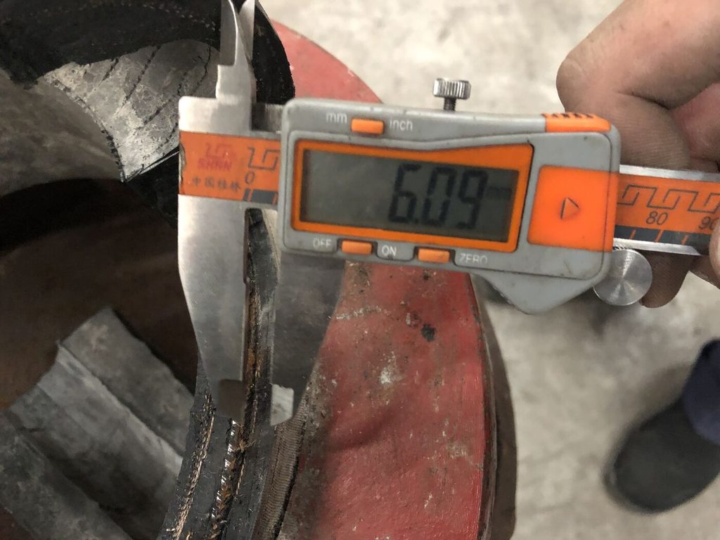
Measuring neck wall thickness during dissection.
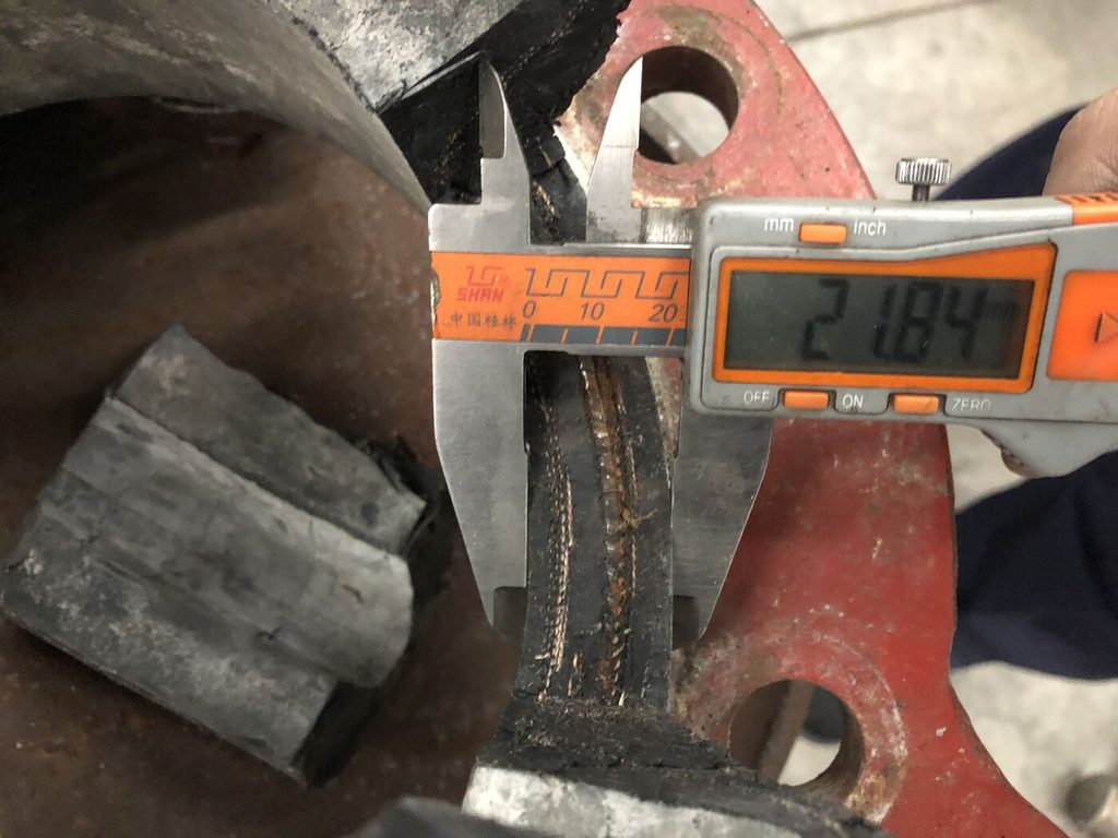
Cord-to-rubber adhesion strength test (119 N/cm measured) on the neck section.
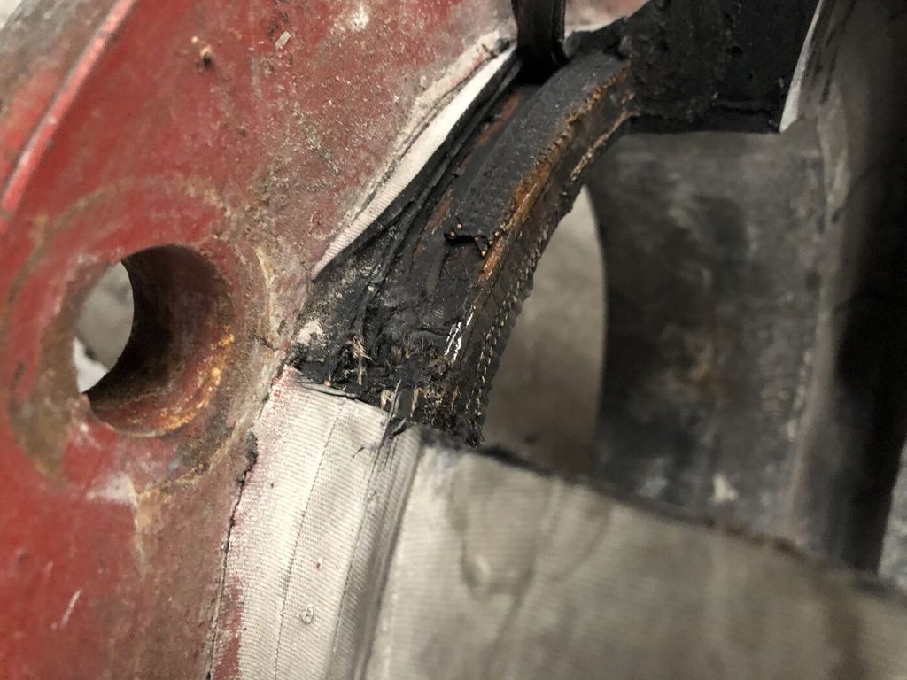
Flange collar cross-section, showing the collar height and cord-ply-to-collar transition.
Sphere Body (Convolution) Structure
| Measurement | Value |
|---|---|
| Convolution total thickness | 11mm (inner liner 2.7mm + middle ply 2.4mm + outer cover 2.0mm) |
| Cord ply between inner liner and middle ply | 1 ply; splits into 3 cords near the convolution centerline (~9mm from center) |
| Cord ply between middle ply and outer cover | 1 cord |
| Sphere-to-neck overlap/splice zone | Cord ply count jumps to 3 plies; inner liner thickness at this zone: 12.6mm |
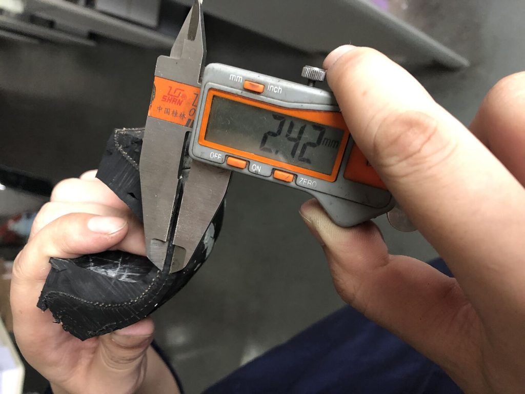
Convolution wall cross-section, measured layer by layer to map the ply structure.
Root Cause: A Structural Discontinuity at the Splice Zone
Lining up the crack location against the dissection data, the cause is unambiguous:
- Abrupt cord-ply transition. The convolution carries essentially 1 cord ply, while the overlap zone where it splices into the neck jumps to 3 plies. That step-change in reinforcement creates a sudden stiffness discontinuity — a textbook stress concentration point.
- Steep thickness gradient. Total wall thickness goes from 11mm at the convolution to 21.8mm at the neck, transitioning within a short splice zone. During molding, rubber flow through this complex, rapidly-changing cross-section is harder to control, increasing the risk of incomplete compaction, trapped air, or a weak bond line at the splice.
- Cyclic fatigue at the discontinuity. In service, an expansion joint continuously absorbs axial, lateral, and angular movement. A stiffness discontinuity subjected to repeated cyclic loading is exactly where fatigue cracks initiate and propagate — consistent with the 340mm crack found at this exact location.
Conclusion: the failure originated from a cord-ply design discontinuity and incomplete rubber compaction at the sphere-to-neck splice zone — a combined structural design and molding-process issue, not a raw material defect.
Our Manufacturing Fix
Based on this analysis, we made the following changes to our production process for wound-type expansion joints:
1. Graduated cord-ply transition. Instead of stepping directly from 1 ply to 3 plies, the splice zone now uses a staged/graduated ply transition, eliminating the abrupt stiffness jump.
2. Local reinforcement at the splice zone. An additional cushion layer or reinforcing ply is added at the sphere-to-neck overlap, increasing local thickness to distribute stress rather than concentrate it.
3. Optimized vulcanization parameters. Molding pressure and dwell time at this geometrically complex zone were adjusted to ensure full rubber flow and compaction, eliminating trapped air and bonding defects.
4. Higher adhesion strength standard. The measured 119 N/cm cord-to-rubber adhesion is now held to a tighter internal minimum (≥130 N/cm) to improve interlaminar reliability at the source.
5. Mandatory NDT inspection at the splice zone. X-ray or ultrasonic non-destructive testing at the sphere-to-neck overlap is now a required release checkpoint, specifically screening for voids, delamination, and cord misalignment before the product ships.
Why We Publish Failure Analyses Like This
This is how our quality system actually works: every field-returned part goes through structural dissection, the data gets compared against design intent, and confirmed root causes get written into the production standard — not just noted and forgotten. That is how a stiffness discontinuity at one splice zone on one part number turns into a permanent process improvement across our expansion joint line.
If you are specifying wound-type rubber expansion joints for a demanding application — high cycle counts, large movements, or critical piping systems — we’re happy to walk through your working conditions and how our carcass design and QC checkpoints apply to your spec.
Henan Devel Fluid Equipment Co., Ltd. designs and manufactures custom rubber expansion joints, non-metallic (fabric) expansion joints, metal expansion joints/corrugated metal hoses, and rubber check valves for international buyers, DN32–DN5000, to ASME/DIN/JIS standards. Contact us to discuss your application.