Fabric Belt Replacement Guide for Non-Metallic Expansion Joints: Step-by-Step Installation & Maintenance
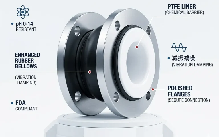
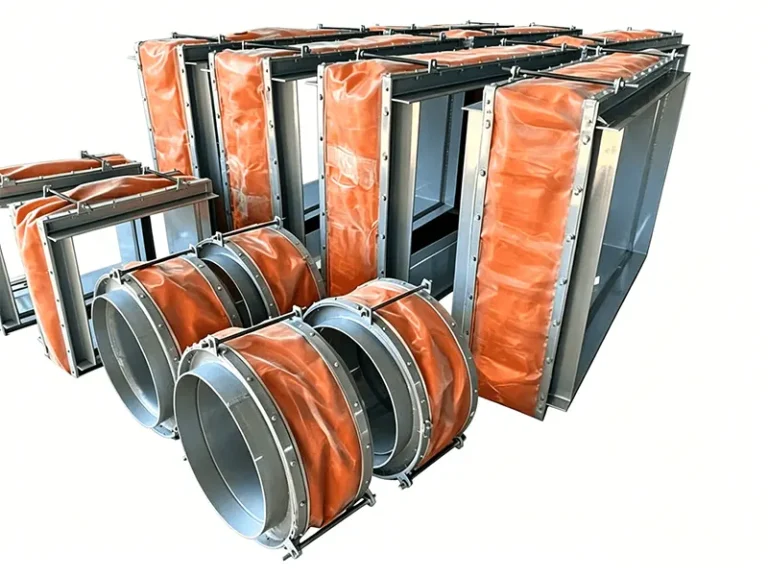
Non-metallic expansion joints — also known as fabric compensators or fabric expansion joints — are critical flexible connectors in industrial ducting systems. Their core sealing element, the fabric belt (flexible sealing diaphragm), is a multi-layer composite of synthetic rubber, fluoroplastics, fiberglass fabrics, PTFE membranes, stainless steel wire mesh, and thermal insulation materials. Over time, exposure to high temperatures, corrosive gases, abrasive particulates, and cyclic mechanical stress degrades the belt, making replacement necessary to maintain system integrity.
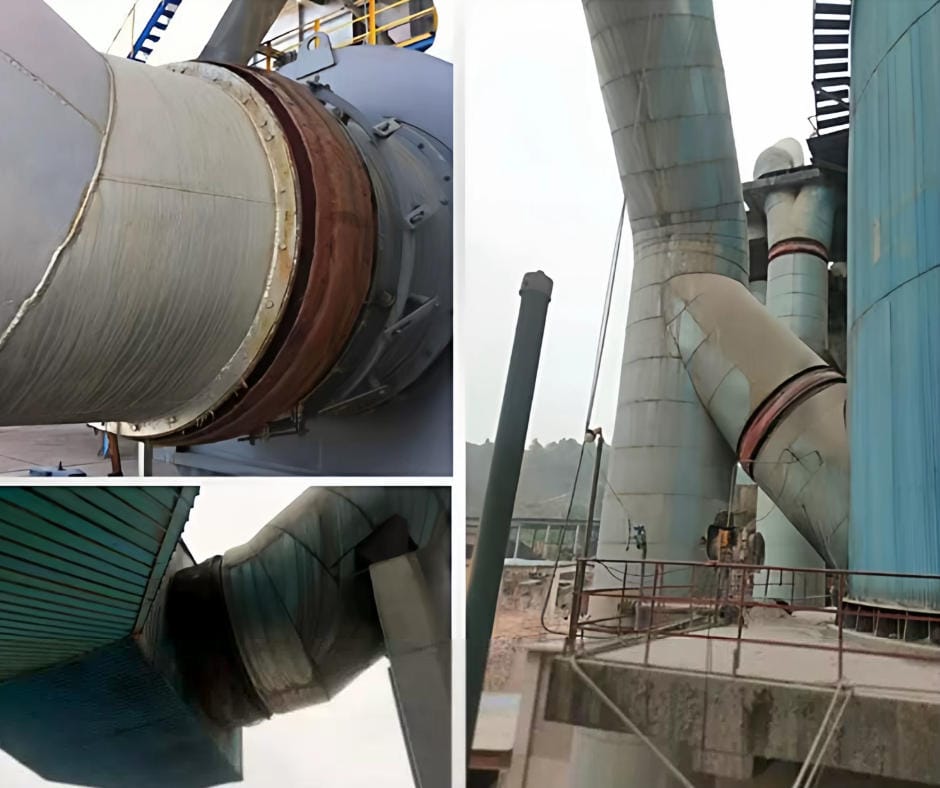
This guide provides a complete, field-tested procedure for replacing the fabric belt on non-metallic expansion joints — covering preparation, safe removal of the old belt, correct installation of the new belt, bolt clamping sequences, and post-installation inspection. Whether you operate a flue gas desulfurization (FGD) system, cement kiln, steel mill, or petrochemical plant, this guide applies to your ducting environment.
1. Pre-Work Preparation & Safety
Before any work begins on the expansion joint, thorough preparation ensures a safe, efficient replacement with minimal downtime. Skipping preparation steps is the leading cause of rework and installation failures.
1.1 Verify Replacement Components
- Confirm dimensions: Measure the existing expansion joint’s outer diameter (for circular joints) or frame dimensions (for rectangular joints), belt width, and bolt-hole spacing. Cross-check against the replacement belt specifications.
- Verify technical parameters: Ensure the replacement belt matches the original design in terms of temperature rating, pressure class, chemical resistance, and layer composition. DEVEL fabric belts are available in 7-layer fluororubber and silicone-coated fiberglass configurations.
- Inspect clamping bars and fasteners: If reusing the original clamping bars (back-up bars), inspect them for corrosion, warping, or bolt-hole elongation. Replace any deformed components. Verify that bolt grade, nut type, and washer specifications match project requirements.
1.2 Site Safety Preparation
- Clear all flammable materials from the work area within a 3-meter radius.
- Position fire extinguishers at accessible locations around the work zone.
- Set up scaffolding or access platforms rated for the required working load. Ensure stable, level footing.
- Verify power supply for electric torque wrenches and lighting.
- Prepare oxy-acetylene cutting equipment for seized or corroded fasteners.
- Use protective sheeting to shield the new fabric belt and surrounding equipment from welding spatter, cutting slag, and debris.
- All personnel must wear appropriate PPE: hard hats, safety glasses, heat-resistant gloves, and steel-toe boots.
⚠ Critical Safety WarningNever use the expansion joint’s transport tie rods or limit rods as lifting points. For joints exceeding 1 m² cross-sectional area, use spreader bars to distribute the load evenly and prevent frame distortion.
2. Removing the Old Fabric Belt
Systematic removal of the old belt preserves reusable components and prevents damage to the structural steel frame. Work methodically — mark everything before disassembly.
2.1 Unbolt and Extract
- Using a spanner, impact wrench, or — for seized bolts — oxy-acetylene cutting equipment, remove all fasteners securing the clamping bars around the entire perimeter.
- Carefully remove the clamping bars (back-up bars). If bars are to be reused, mark each bar’s position and orientation sequentially (e.g., “T-1, T-2, T-3…” for top side; “B-1, B-2…” for bottom side) to ensure the bolt holes realign perfectly during reassembly.
- Extract the old fabric belt. If it is heavily degraded, cut it into manageable sections for disposal.
2.2 Handle Insulation Materials
- For joints equipped with internal insulation bolsters (thermal pillows): carefully remove each pillow and inspect its condition.
- Reusable pillows — those that remain dry, intact, and free of chemical saturation — should be stored separately in a clean, dry location.
- Degraded pillows — those showing moisture ingress, hardening, crumbling, or chemical attack — must be replaced. Do not reuse compromised insulation; it will undermine the new belt’s thermal protection.
💡 Pro Tip: Mark EverythingMark the positions of clamping bars, bolt holes, and insulation pillow locations before removal. A few minutes of labeling saves hours of trial-and-error during reassembly — especially on large rectangular joints where bar lengths and hole patterns may vary by side.
3. Frame & Component Inspection
With the old belt removed, this is the only opportunity to thoroughly inspect the structural components that will support the new belt. Overlooked frame damage is a common root cause of premature belt failure.
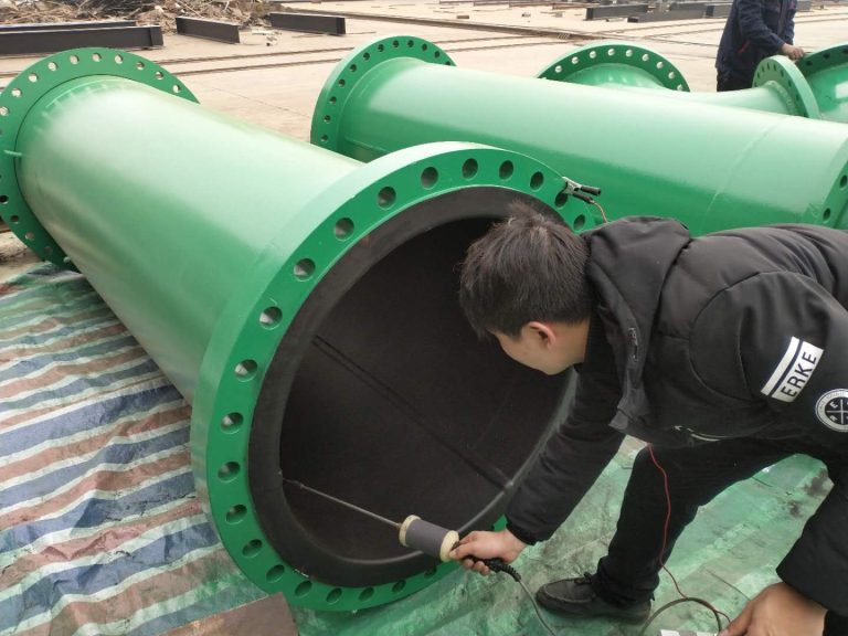
- Inspect the flow liner / baffle (inner sleeve): Check for deformation, corrosion, or perforation. Repair or replace damaged sections.
- Check the counter-flange and metal frame: Look for warping, pitting, or weld cracks. The flange face must be flat and smooth — any irregularities will create uneven clamping pressure and leak paths.
- Verify frame alignment: The two interface flanges must maintain coaxial alignment within ±5 mm. Angular deviation must not exceed ±1°. Torsional deviation must not exceed 2.5°.
- Clean all mating surfaces: Remove rust, scale, old gasket residue, and debris from flange faces and clamping bar contact areas. Use a wire brush or grinder, then wipe clean.
- Apply anti-corrosion treatment: Prime and paint any bare metal surfaces before installing the new belt.
4. Installing the New Fabric Belt
Correct belt installation is the single most important factor determining service life. Follow these steps precisely — particularly regarding belt orientation, insulation placement, and wrinkle prevention.
4.1 Install Internal Insulation First
- If the joint design includes internal insulation layers, install these before positioning the outer fabric belt.
- Begin with the inner-most insulation layer: position insulation anchor pins (if applicable), then install the innermost thermal blanket — typically ceramic fiber or mineral wool — wrapped in stainless steel wire mesh.
- Add subsequent insulation layers in sequence, securing each layer flat and evenly with insulation retaining pins or clips. Ensure no gaps or thin spots — thermal bridging will cause localized overheating of the belt.
4.2 Position and Secure the Fabric Belt
- Orientation matters: The smooth (gas-tight) side of the belt faces the process medium (inside the duct). For belts with an integrated metal wire mesh protective layer, the mesh faces the atmosphere side (outside). Verify the flow direction arrow on the belt matches the process flow direction.
- Lay the belt flat against the metal frame flange surface. Eliminate all wrinkles and folds — even small wrinkles will develop into leak paths under thermal cycling.
- Start installation from the bottom of the joint (for vertical joints) or from one end (for horizontal ducts). Work progressively around the perimeter, keeping the belt taut but not stretched.
- For horizontal duct joints: position the belt’s outer seam at the top or upper side of the joint to prevent water ingress.
- NEVER stretch the belt during installation. Fabric belts are designed with a small built-in allowance (typically ~100 mm excess circumference) to permit uniform compression — not tension — during clamping.
4.3 Belt Splicing (Field Joints)
If the belt requires field splicing (e.g., for very large diameters where a single-piece belt is impractical, or for replacement belts supplied as open lengths):
- Use the single-layer staggered overlap method — NOT full-thickness butt joints. Each layer should overlap by a minimum of 300 mm (or no less than the belt width for narrow belts).
- Apply adhesive (fluororubber-compatible) between the overlapping surfaces of the innermost and outermost layers.
- Allow adhesive to cure for a minimum of 24 hours before installing clamping bars.
- Position the splice joint at the top or upper side of the expansion joint.
⚠ Important: Never Butt-Join Belt LayersDo not align all layer splices at the same location. Each layer’s splice must be staggered relative to adjacent layers to maintain gas-tight integrity. Aligned splices create a single weak plane that will fail under thermal cycling.
5. Clamping Bar Assembly & Bolt Torque Sequence
The clamping system — back-up bars, bolts, nuts, and washers — is what transforms the flexible belt into a pressure-tight seal. Proper assembly technique is non-negotiable.
5.1 Clamping Bar Placement
- Position the clamping bars on both sides of the belt, ensuring bolt holes align precisely with the flange holes. Misalignment will cause bolt thread damage and uneven clamping.
- The clamping bar should extend evenly beyond the belt edge on all sides.
- For joints with sealing gaskets, position the gasket between the belt and the flange face. Gasket splices must be cut at a 45° angle (scarf joint) for smooth transition — never butt-joined at 90°.
5.2 Bolt Insertion & Orientation
- Insert bolts through the assembly in the following order: flange → clamping bar → fabric belt → clamping bar → counter-flange.
- For flanged-type (bolted) expansion joints: the threaded end of the bolt must face outward (away from the belt), with the bolt head on the process side. This prevents the bolt shank from contacting and abrading the belt during operation.
- Use heavy-duty washers under both the bolt head and nut to distribute clamping force.
5.3 Star-Pattern Torque Sequence
This is the most critical step in the entire installation. The star (cross-diagonal) tightening sequence ensures uniform compression around the entire perimeter, preventing localized over-compression that crushes the belt and under-compression that creates leak paths.
- Hand-tighten all bolts first — just enough to hold the assembly in place.
- Apply the star sequence: tighten opposing quadrants in a diagonal pattern. Start from the center of each side and work outward. For rectangular joints, tighten in this order: center of top → center of bottom → center of left → center of right → then work diagonally toward corners.
- Torque in stages: First pass at ~30% of target torque, second pass at ~60%, final pass at 100% of specified torque value.
- Use a calibrated torque wrench. If access restrictions prevent using an electric torque wrench, manual torque wrenches must still achieve the specified value — never skip the torque check.
⚠ Do NOT OvertightenThe correct compression is indicated by aslight, uniform convex bulgeappearing on the belt body at the clamping interface. If the belt appears crushed, flattened, or if the rubber shows signs of extrusion, the bolts are overtightened. Overtightening destroys the belt’s internal structure and leads to premature edge-tear failure.
5.4 Special Considerations for Rectangular & Large Joints
- Rectangular flanged joints: Secure the corners first, then work along each side, evenly distributing any circumferential clearance between the belt and frame.
- Circular flanged joints (vertical installation in horizontal ducts): Start from the bottom, fix symmetrical points, and work upward, evenly distributing belt material and absorbing installation clearance as you go.
6. Special Installation Cases
6.1 Pre-Assembled Expansion Joints (Factory-Bonded Belt)
For expansion joints delivered with the belt already installed (except the final splice), protect the belt from damage during frame assembly. Once the frame is welded and aligned, complete the belt splice at the designated joint location (top or upper side), apply adhesive, and secure with clamping bars after the 24-hour curing period.
6.2 Loose-Components Delivery (Field Assembly Required)
When the expansion joint is supplied as separate components:
- Assemble and weld the frame sections according to the engineering drawings. Grind all weld seams smooth and flush — any weld roughness will abrade the belt.
- Apply anti-corrosion coating to the frame and allow it to cure fully. The coated surface must be smooth and even.
- Apply the sealing gasket to the frame surface per specifications.
- Fill internal insulation cavities uniformly — no voids permitted.
- Position the belt, align the splice location, and match-drill the bolt holes through the belt, gasket, and clamping bars together. This ensures perfect hole alignment.
6.3 Welding Near the Fabric Belt
If welding must be performed after belt installation, the belt surface temperature must not exceed 150°C. Use thermal shielding (welding blankets, heat sinks) and monitor temperature continuously. Protect the belt from weld spatter, slag, and grinding sparks with fire-resistant covers.
7. Post-Installation Inspection & Testing
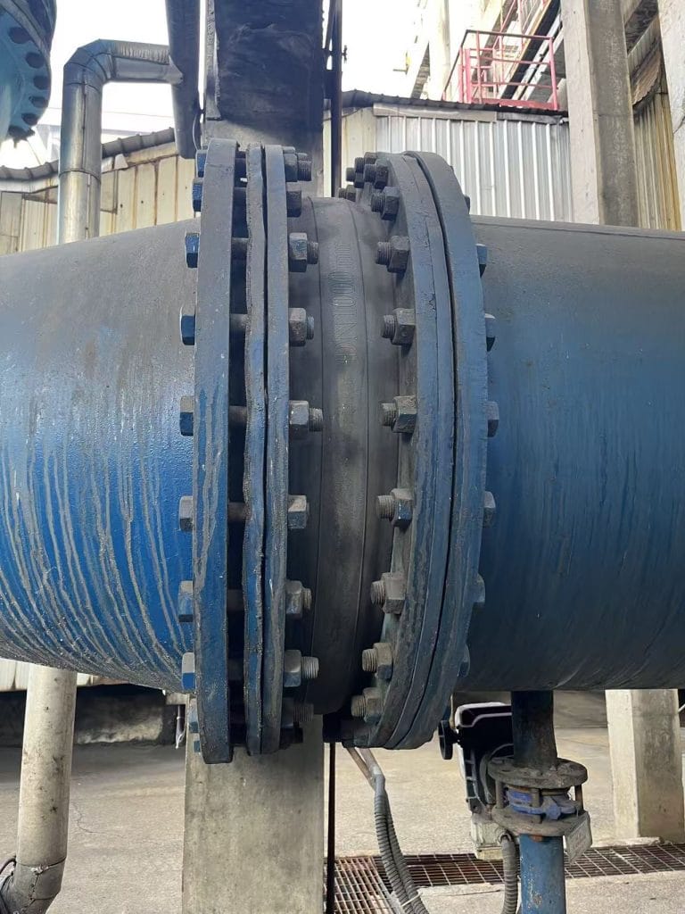
- Visual inspection of the entire perimeter: Verify uniform gap closure between clamping bars and flange faces. Check for any visible gaps, wrinkles, or uneven compression.
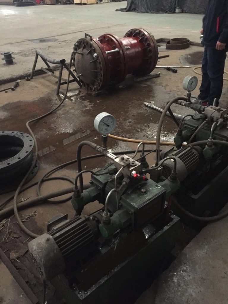
- Low-pressure leak test: Before system startup, conduct a low-pressure air or smoke test to confirm gas-tight integrity. Soap-bubble testing at all clamped interfaces can identify micro-leaks.
- Remove transport restraints: After installation is complete and all piping is connected, remove the yellow-marked transport tie rods and limit stops. Failure to remove these will constrain thermal expansion and cause structural damage during operation.
- Clear the duct interior: Remove all debris, tools, and foreign objects from inside the duct. For joints without flow liners, pay special attention to debris that could erode the belt during operation.
- Document the installation: Record final torque values at multiple points around the perimeter. Take photographs of the completed installation for maintenance records. This documentation is invaluable for future replacement cycles.
8. Ongoing Maintenance & Expected Service Life
8.1 Routine Inspection Schedule
| Inspection Frequency | Check Items |
|---|---|
| Monthly (visual walk-around) | External belt surface condition, visible cracking, discoloration, bolt tightness indicators |
| Every 6 months | Detailed belt inspection, bolt torque re-check (re-torque after initial thermal cycling), clamping bar alignment |
| Annually (during planned shutdown) | Full internal and external inspection, insulation bolster condition assessment, leak test, frame corrosion check |
8.2 Re-Torque After Commissioning
After the first thermal cycle (plant startup and cool-down), re-torque all clamping bolts to the specified value. Thermal expansion and contraction cause the belt and gasket materials to settle, resulting in torque relaxation. This re-torque step is essential for long-term seal integrity.
8.3 Service Life Expectations
| Belt Type | Typical Service Life | Key Factors Affecting Longevity |
|---|---|---|
| Silicone-Coated Fiberglass Belt | 3–5 years (up to 10 years outdoor) | UV exposure, temperature cycling range, mechanical abrasion |
| Fluororubber (FKM) 7-Layer Composite Belt | 3–5 years (longer in stable conditions) | Chemical concentration, peak temperature excursions, pressure cycles |
8.4 Operational Do’s and Don’ts
- Do not allow metal objects, stones, or hard tools to strike or rest against the fabric belt.
- Do not expose the external belt surface to corrosive chemicals, solvents, or oils.
- Do provide full protective shrouding when conducting maintenance work (grinding, welding, chemical cleaning) within 3 meters of the expansion joint.
- Do not use the expansion joint to compensate for piping misalignment during installation — the joint absorbs operational displacement, not construction errors.
- Do not strike an arc on any part of the expansion joint assembly.
9. Frequently Asked Questions
Q: Can I reuse the old clamping bars?
Yes, provided they pass a thorough inspection. Check for: (a) straightness — warped bars will not clamp evenly; (b) bolt-hole condition — elongated or corroded holes compromise clamping force; (c) material thickness — bars thinned by corrosion may not provide adequate stiffness. When in doubt, replace.
Q: What if I cannot achieve the specified torque due to limited access?
Use offset adapters, crowfoot wrenches, or hydraulic torque tools designed for tight-access applications. If absolutely no torque tool can access a bolt, mark it clearly and return to torque it after adjacent bolts are tightened — but never leave any bolt un-torqued. A single loose bolt creates a leak path and a tear initiation point.
Q: How do I store a spare fabric belt before installation?
Store fabric belts indoors, in their original packaging, away from direct sunlight, moisture, and temperature extremes. Do not stack heavy objects on top of the belt. Do not store outdoors — even brief exposure to rain, construction debris, or foot traffic can damage the belt’s outer layer. Belts should be stored flat or rolled at the manufacturer’s recommended minimum bend radius.
Q: What is the correct belt orientation — which side faces the process?
The smooth, gas-tight membrane side (typically fluororubber or PTFE surface) faces the process medium. The metal wire mesh side (when present) faces the atmosphere. Always check the belt’s labeling — DEVEL belts include directional markings and installation tags.
Q: How soon can the system be started after belt replacement?
If no adhesive splicing was performed, the system can be started immediately after completing the post-installation inspection and leak test. If adhesive was used for belt splicing, allow a minimum 24-hour cure time at ambient temperature before pressurizing or heating the system.
Need a Replacement Fabric Belt?
DEVEL manufactures 7-layer composite fabric belts engineered for extreme temperatures up to 1000°C, with PTFE dual-barrier zero-permeation technology. Custom dimensions from DN100 to DN5000, circular or rectangular.
View Fabric Belt Specifications & InquireOr contact our technical team directly for application-specific recommendations.