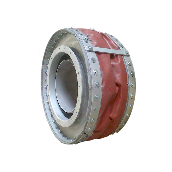
Round Fabric Expansion Joint (Circular Non-Metallic)
- 1.Multi-layer composite construction with PTFE chemical barrier membrane and ceramic fiber insulation blanket for high-temperature flue gas service.
- 2.Simultaneous multi-plane movement: axial compensation up to 215mm and lateral offset up to 85mm in a single joint.
- 3.Wide temperature capability: -35°C to +575°C standard (up to +1000°C with special high-temperature design).
- 4.Low-pressure rated (±0.35 bar) specifically engineered for ducting systems where pressure loads are minimal.
- 5.Massive diameter range from DN100 to DN10000+ to suit any circular, oval, or custom duct configuration.
- 6.Near-zero reaction force transmission protects fans, ductwork, and support structures from mechanical stress.
- 7.FGD/SCR compliant PTFE membrane provides total impermeability to acid condensates and corrosive flue gases.
- 8.Ideal for gas turbine exhaust, boiler flue gas ducts, cement kilns, steel mill dust extraction, and waste-to-energy applications.
Round Fabric Expansion Joint (Circular Non-Metallic)
DEVEL Round Fabric Expansion Joint is a high-performance flexible connector specifically engineered for large-diameter circular ducting systems where conventional metallic bellows face fatigue limits due to extreme thermal expansion, multi-plane displacement, or oversized dimensions.
Constructed from multiple layers of specialized technical fabrics and elastomers — including PTFE chemical barrier membranes, ceramic fiber insulation blankets, high-tensile structural plies, and silicone/fluorine-coated weatherproof outer protection — these joints provide a robust solution for absorbing thermal expansion, mechanical vibration, and structural misalignment in low-pressure, high-temperature gas handling environments.
Unlike rigid metallic alternatives that transfer significant reaction forces into the supporting structure and require expensive thrust-restraint frameworks, fabric joints exert negligible spring rates and can handle simultaneous axial (up to 215 mm), lateral (up to 85 mm), and angular displacements with virtually zero system stress.
Available in diameters from DN100 to DN10000+ with operating temperatures up to +575°C standard (+1000°C optional), they represent the preferred choice for power plant flue gas ducts, gas turbine exhaust systems, boiler stack inlets, FGD/SCR units, cement kiln lines, metallurgical smelting furnaces, waste-to-energy facilities, and any application demanding reliable compensation for massive thermal movements without compromising ductwork integrity or requiring heavy structural reinforcement.
Key Features at a Glance
- Comprehensive Multi-Plane Movement Compensation
The composite fabric architecture is designed to handle significant axial, lateral, and angular displacements simultaneously. This multi-plane flexibility is critical in systems where rigid metallic bellows may face fatigue limits from combined thermal growth vectors. - Extreme Thermal Integrity & Resilience
Depending on material configuration (PTFE, silicone-coated fiberglass, or ceramic fiber blankets), joints maintain full structural integrity in continuous operating temperatures ranging from -35°C ambient up to +575°C standard, with special designs available up to +1000°C. - Superior Chemical Inertness & Acid Resistance
Utilizing high-grade PTFE (Teflon®) liner membranes, these joints offer exceptional resistance to corrosive flue gases and acid dew point condensation, ensuring extended service life in FGD desulfurization and SCR denitrification systems. - Optimized Vibration Isolation & Acoustic Damping
The non-metallic construction acts as a natural acoustic barrier, effectively dampening fan-induced noise transmission and preventing the propagation of mechanical shocks through the ductwork network. - Minimal System Stress & Zero Thrust Load
Due to extremely low spring rate of technical fabrics, the joint exerts negligible reaction forces on adjacent duct flanges and supporting structures, eliminating the need for costly thrust-restraint frameworks and enabling more streamlined, cost-effective system designs. - Massive Diameter Range & Custom Sizing
Available from DN100 (4″) to over DN10000+ (394″+), with no practical upper limit. Lengths are project-specific and fully customizable. Oversized units can be supplied in split segments for field assembly when shipping or access constraints apply. - Robust Flanged or Weld-Sleeve End Connections
Shell termination options include carbon steel or stainless steel welding sleeves (for direct weld-in installation) and drilled flanges matching ANSI/EN/DIN standards. All metal components are epoxy-coated for corrosion protection in harsh environments. - Multi-Layer Composite Construction
Five functional layers working in concert: (1) Outer silicone/fluorine coating for UV/weather protection; (2) High-tensile glass fiber or aramid structural ply; (3) PTFE barrier membrane for zero permeability; (4) Ceramic fiber thermal insulation blanket; (5) Optional stainless steel inner liner for erosion protection.
Key Technical Advantages
- ► Simultaneous Displacement Handling: Unlike single-axis metal bellows, fabric joints absorb axial compression/extension, lateral offset, and angular rotation all at once — ideal for complex duct routing with multi-directional thermal growth.
- ► Weight Advantage: Fabric construction is approximately 10% of equivalent metal bellow weight — critical for elevated duct supports, crane-lifted installations, and seismic-sensitive structures.
- ► No Maintenance Required: No moving parts, no lubrication, no periodic re-tightening. Once installed, these maintenance-free joints operate reliably throughout their design life without service intervention.
- ► Rapid Replacement Capability: Lightweight design allows fast field replacement during outages. Split-segment option enables replacement through manways without dismantling entire duct sections.
- ► Acoustic Performance: The multi-layer fabric structure provides inherent sound attenuation (typically 10–25 dB reduction), reducing or eliminating the need for separate silencers in many applications.
- ► Corrosion-Free Core: With no metallic flexible elements exposed to corrosive gases, the risk of stress corrosion cracking (SCC) and chloride-induced failure is completely eliminated.
Technical Specifications
| Parameter | Standard Value | Optional / Remarks |
|---|---|---|
| Temperature Range | -35°C to +575°C | Up to +1000°C (with special design) |
| Pressure Range | -0.35 to +0.35 bar (±350 mbar) | Higher on request |
| Diameter Range | DN100 to DN10000+ | No practical upper limit |
| Length | Project Specific | As required by movement demand |
| Movement Axial | Up to 215 mm | More with special design |
| Movement Lateral | Up to 85 mm | More with special design |
| Radial / Angular Movement | Consult factory | Combined/large-diameter solutions |
| End Connection Types | Welding Sleeve / Drilled Flange | ANSI / EN / DIN compatible |
| Design Standards | ASME B31.1, ISO 15547, EJMA guidelines for non-metallic expansion joints | |
Standard Size Reference
| Nominal Size | Duct Diameter (mm) | Typical Face-to-Face L (mm) | Max Axial Movement (mm) | Max Lateral Movement (mm) | Flange / Sleeve Type |
|---|---|---|---|---|---|
| DN100 | Ø108 | 150–250 | 50 | 25 | Weld Sleeve |
| DN200 | Ø219 | 200–300 | 75 | 40 | Weld Sleeve / Flange |
| DN400 | Ø406 | 250–350 | 100 | 50 | Flange PN6/10 |
| DN600 | Ø610 | 300–450 | 125 | 60 | Flange PN6 |
| DN800 | Ø813 | 350–500 | 150 | 70 | Flange PN6 |
| DN1000 | Ø1016 | 400–550 | 175 | 75 | Weld Sleeve / Custom |
| DN1500 | Ø1520 | 450–650 | 200 | 80 | Split Segment Option |
| DN2000 | Ø2020 | 500–750 | 215 | 85 | Split Segment Option |
| DN3000+ | Custom | Project Specific | Per Design | Per Design | Field-Assembled Segments |
Installation Guidelines & Engineering Notes
Pre-Installation Inspection: Upon receipt, verify that fabric surface is free from cuts, punctures, or delamination. Check that flange faces are clean, parallel, and within specified tolerance. Inspect bolt holes for proper alignment and thread condition.
Alignment & Positioning: Center the joint on the duct axis before tightening. Misalignment exceeding 5% of nominal diameter will cause uneven loading and premature fabric fatigue. Use temporary support during bolting if the unit is heavy or oversized.
Bolting Procedure: Tighten bolts in a star-pattern sequence (opposite quadrants first) to uniform torque specification. Do not over-compress — the fabric body should remain slightly convex after final torque. Over-compression restricts movement capability.
Pressure Testing: Conduct initial leak test at reduced pressure (max 50% of rated pressure) before full commissioning. Gradually ramp to design pressure while monitoring for fabric bulging beyond acceptable limits.
Thermal Cycling: Allow adequate time for the duct system to reach thermal equilibrium before locking permanent restraints. For systems with frequent start-stop cycles (>1 per day), specify enhanced fatigue-rated fabric construction.
Typical Applications
Boiler Flue Gas Ducts
Stack Inlet Connections
FGD Desulfurization Units
SCR Denitrification Systems
Large-Scale Dust Collection Units
Cement Plant Kiln Lines
Metallurgical Smelting Furnaces
Waste-to-Energy Facilities
Power Generation Cooling Air Ducts
Marine Exhaust Gas Systems
Industrial HVAC Large-Diameter Runs
Product Tags
Round Fabric Bellows
Non-Metallic Expansion Joint
Circular Flexible Connector
High Temperature Duct Joint
PTFE Lined Fabric Joint
Ceramic Fiber Insulated
Flue Gas Compensator
Gas Turbine Duct Connector
FGD System Flexible Joint
SCR Duct Expansion Joint
Zero Reaction Force Joint
Vibration Isolation Duct
Silicone Coated Fiberglass
Request a Custom Quote for Your Project
Factory-direct pricing available. DEVEL engineering team ready to assist with material selection, sizing calculations, and installation guidance.