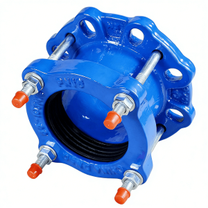
Heavy-Duty Dismantling Joint (Type C2F)
1.Double-flanged power transmission and restraint joint designed for pump, valve, and equipment connections requiring secure thrust restraint and length adjustment.
2.High-tensile Grade 8.8 tie rods (hot-dip galvanized or A4 stainless steel) prevent pipe pull-out under pressure thrust loads.
3.Conical EPDM or NBR rubber gasket delivers uniform circumferential compression and zero-leak service across all pressure ratings.
4.Quick-adjust design allows valve installation and removal without pipe cutting — create withdrawal clearance by retracting the movable sleeve.
5.DN50–DN4000 (2″–160″) with PN10–PN40 / Class 150–300 pressure ratings and Ductile Iron or Carbon Steel body.
6.WRAS-approved Fusion-Bonded Epoxy (FBE) coating (≥250μm) for potable water service and buried pipeline installation.
7.Installed length adjustment range of ±15–25mm compensates for pipe misalignment, thermal expansion, and installation tolerance accumulation.
8.Full restraint design transfers thrust loads directly to the tie rods and anchor flanges — no pipe shoulder reliance required.
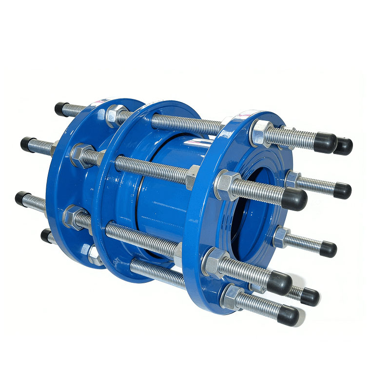
Heavy-Duty Dismantling Joint (Type C2F)
DEVEL C2F Series Dismantling Joint is a premium double-flanged power transmission and restraint solution engineered for high-pressure pipeline systems requiring seamless installation, adjustment, and maintenance of pumps, valves, meters, and other critical equipment.
The joint features a heavy-duty rigid carbon steel or ductile iron body with high-tensile full-thread tie rods that form a rigid restraint system once installed — ensuring the total hydraulic pressure thrust is safely transmitted through the tie rod assembly while protecting the pipeline from stress concentration and preventing longitudinal displacement at the connection point.
A precision-engineered conical rubber gasket system creates a reliable leak-proof 360° circumferential seal under all operating conditions.
The C2F design provides quick adjustability for simplified valve installation and removal, making it an indispensable component in large-scale water supply networks, pumping stations, industrial fluid loops, and any application where future equipment access is anticipated.
Key Features at a Glance
- Rigid Power Transmission & Thrust Restraint
Once bolted into position with tightened tie rods, the C2F acts as a fully rigid restraint member that transmits the entire hydraulic thrust load through its high-tensile Grade 8.8 tie rods directly to the pipeline anchor or equipment flange. This prevents longitudinal displacement, protects pump nozzles and valve bodies from excessive end-load forces, and eliminates the need for separate thrust blocks at each connection. - Conical Rubber Gasket Sealing Technology
A precision-engineered conical rubber gasket ring is compressed between the movable sleeve and the fixed flange body to create a uniform 360° leak-proof seal. The conical profile ensures progressive sealing as internal pressure increases — higher pressure pushes the gasket tighter against the sealing surface, providing self-energizing performance that maintains bubble-tight integrity even under cyclic loading conditions. - Quick Adjustability for Installation & Maintenance
The adjustable-length design allows on-site dimension compensation for pipe fabrication tolerances, thermal expansion variations, and equipment positioning errors. During maintenance cycles, simply loosening the tie rod nuts enables axial retraction to create sufficient clearance for valve or pump removal without cutting pipe sections — dramatically reducing downtime during scheduled overhauls or emergency repairs. - High-Tensile Full-Thread Tie Rod System
Equipped with high-strength galvanized carbon steel or optional stainless steel tie rods manufactured to Grade 8.8 tensile specification. Full-thread design allows unlimited length adjustment within the joint’s stroke range. Rod sizing scales with diameter — from M14 (DN65–DN150) up to M64 (DN3800+), with quantity increasing proportionally to ensure uniform force distribution across the flange face. - Dual Flange Interface Compatibility
Both ends feature standard flat-face or raised-face flange drilling patterns fully compatible with ISO 7005, EN 1092-1, and ANSI/AWWA B16.5 flange standards. This universal interface allows direct bolting to valves, pumps, flow meters, check valves, butterfly valves, and virtually any flanged piping component without transition spools or adapters. - WRAS-Approved Epoxy Corrosion Protection
The complete external surface is coated with a WRAS-approved fusion-bonded epoxy resin layer available in Blue or Black finish options with a minimum dry film thickness of 250 microns. WRAS certification confirms coating safety for potable water contact applications. For aggressive environments, optional polyurethane topcoat or increased FBE thickness (up to 500μm) is available. - Rigorous Factory Testing Protocol
Every unit undergoes dual-stage quality verification: hydrostatic pressure testing at 1.5× nominal working pressure for structural integrity validation (minimum 30-minute hold), followed by pneumatic testing at 1.1× rated pressure for bubble-tight seal confirmation. Test certificates and material traceability documentation provided as standard with each shipment. - Extreme Size Range & Customization
Manufactured from DN50 (2″) up to an extraordinary DN4000 (160″) — one of the widest size ranges available for this product category globally. Standard catalog covers 30 discrete sizes from DN65 to DN4000. Custom dimensions, non-standard flange drillings, special pressure classes, and project-specific material combinations are engineered upon request.
Key Technical Advantages
1. Optimized Force Distribution Engineering: The C2F’s rigid restraint design converts what would otherwise be uncontrolled hydraulic thrust into a predictable, manageable axial compressive load distributed evenly across the flange face via the tie rod array. Finite element analysis (FEA) validated geometry ensures that stress concentrations at flange-to-body transitions remain well below material yield limits — even at PN40 maximum pressure ratings on large diameters (≥DN600).
2. Valve & Pump Protection Function: By acting as a mechanical “fuse” between the pipeline and rotating/reciprocating equipment, the dismantling joint absorbs installation misalignment, vibration transmission, and thermal growth-induced displacement. This protective function extends the service life of downstream equipment seals, bearings, and shaft couplings by reducing fatigue cycling caused by pipeline movement.
3. Global Standards Compliance: Fully compliant with ISO 2531 (Ductile Iron products), ISO 7005 (Metal flanges), EN 545 (Water applications), EN 1092-1 (Steel flanges and joints), and ANSI/AWWA B16.5 (Malleable iron/flanged fittings). Body materials meet EN-GJS-500-7 ductile iron minimum tensile requirements (500 MPa UTS, 350 MPa yield). Third-party inspection (TPI) and witnessed testing available for regulated utility projects.
4. Potable Water Safety Certified: EPDM gasket formulation meets international potable water standards including NSF/ANSI 61, ACS (France), WRAS (UK), and KTW/DVGW (Germany). The epoxy coating system carries WRAS approval confirming suitability for direct contact with drinking water without leaching harmful substances. Complete material certification package provided for regulatory compliance submissions.
Technical Parameters
Dimensions & Size Specifications
Note: Above sizes are manufactured according to Chinese Standard specifications. Non-standard dimensions, custom flange drilling patterns, and extended adjustment ranges are available upon request. Contact our engineering team for custom configuration drawings.
Installation Guidelines & Best Practices
1. Pre-Installation Length Calculation: Determine the required installed length by measuring the face-to-face distance between the two connection points (valve flange to pipe flange, or pump nozzle to anchor flange). Set the C2F dismantling joint to approximately 15–20mm longer than this measured distance to allow adequate compression engagement of the conical gasket when the tie rods are tightened. Never install at maximum extension — always reserve compression travel.
2. Alignment & Centering Procedure: Align both flange faces concentrically before inserting bolts. Use alignment jacks or come-alongs on larger diameters (≥DN600) to hold the equipment in position. Misalignment exceeding ±3mm eccentricity can cause uneven gasket compression and localized stress concentration in the body casting. Verify parallelism of flange faces using feeler gauges at 4 quadrants.
3. Tie Rod Tightening Sequence: Follow a diagonal star-pattern sequence similar to flange bolt tightening. Tighten all nuts progressively in three passes: first pass to 30% torque, second pass to 70%, final pass to 100% specified torque. Do not fully tighten one side before the others — this causes body tilting, uneven gasket contact, and potential leakage paths. Refer to torque table supplied with each unit.
4. Post-Installation Verification & Maintenance Access: After final torque completion, verify that equal thread exposure is visible on opposite tie rod pairs — indicating centered compression. Record the installed length for reference during future maintenance. To remove connected equipment for overhaul, loosen all tie rod nuts equally and retract the movable sleeve to create the necessary withdrawal clearance — no pipe cutting required.
Typical Applications
Pump Station Inlet & Outlet Connections
Industrial Process Fluid Loop Piping
Valve Installation & Removal Interfaces
Power Generation Plant Cooling Water Systems
Wastewater Treatment Headworks & Clarifiers
Desalination Plant High-Pressure Pipelines
Shipyard & Marine Ballast System Connections
Product Tags
C2F Type
Double Flanged Restraint
Power Transmission Joint
Ductile Iron GGG500
Conical Gasket Seal
Tie Rod Restraint
WRAS Epoxy Coated
PN10-PN40
ISO 1092
Valve Installation Aid
Pipeline Repair
Thrust Restraint
Request a Custom Quote for Your Project
Factory-direct pricing available. DEVEL engineering team ready to assist with material selection, sizing calculations, and installation guidance.